With so many injection mold tooling suppliers to choose from some disparity in costs is to be expected, but what are the main drivers of these costs differences and how can you ensure you get the price you should for tool you want?
China has hundreds maybe thousands of injection mold and tool makers to choose from and it seems each one has their own way of quoting your project. The result is five vastly different costs from five companies for the same project. Which to go with?
There are factors other than cost to be considered when choosing a supplier, arguably many of them even more important than price, but how can you can ensure you are getting the right costs for the tools you need and what is affecting these costs.
There are several main drivers of cost, they are;
- Part quality and tolerance
- Part material
- Surface finish
- Quantity required
- Part geometry
- Information
Understandably the higher the quality and tolerance requirements then the higher your tooling costs will be. This needs to be something you look at and decide upon internally, what are incremental gains in quality and tighter tolerances actually worth. You need to make sure the quality and tolerances match the project requirements and no more.
The part material is also going to affect the tooling costs, hard and abrasive materials like glass filled nylons require the tool is made from harder more resilient steels, which will up your prices. Transparent materials have the same effect on choice of steel and also require more processing time during the tool build stage.
Surface finishes can have massive impacts upon the cost of your tools, high polished or transparent finishes require both better quality steels and much more work to achieve than a standard polish. Also any MoldTech or other texture could mean much higher costs for the tools as these require expensive chemical processes.
Quantity of parts required will impact two fold, first in the tool design itself. If you are looking at very high numbers of parts it might make sense to go with multi cavity tools, which are larger and more expensive but will bring part costs down. Also the higher the quantity required the better the steel used to machine the cavity, core and inserts will need to be. Low quantities can often be realized using low grade steels or aluminum bringing costs down.
Undercuts mean side actions, sliders and lifters which means a more complicated tool design, more work and higher costs. If you can reduce these features as much as possible you will save yourself in lead time and costs.
The second main category driving cost is the information you provide to the tool maker, the more complete and detailed this is the more accurate the quote will be and the better the price will reflect what you actually want. This does not necessitate you being an expert or a toolmaker yourself, but it does mean you need to be open, forthcoming and direct with what information you provide. No one knows your project, part or requirements better than you, making sure the toolmaker knows them too is good business sense.
Finally when you receive the quote from your suppliers check to make sure what they have quoted reflects what you want. Most suppliers will detail elements of the quote such as the tool life and type of steel quoted and this will allow you to make sure what they have quoted is in line with what you want.
If you are clear about the requirements most companies prices will reflect this, then the main determiner of price becomes the company itself.
- What are their overheads and profit margins?
- How busy are they?
- How much do they want your business?
- How much of the project are they able to do in house?
More often than not a bigger company with larger overheads to cover will quote a higher cost than a smaller company though this is not always true. Larger companies may be able to work with a lower profit margin across the board as they are running more projects in total.
How busy is the company that is quoting for you, this is difficult to assess without a visit, but asking wont hurt. The less busy the company the better your negotiating position becomes.
How much does the company want your business. This matters a lot and the better able you are to convince the company that you are a long term and reliable contact the better costs you should get.
How much of your project is the company able to do in-house? Very few companies are able to do everything and there will be steps that need to be outsourced, on the whole the less the company needs to rely on outside resources the cheaper your costs may be.
These are outside the control of most purchasers but getting as much information as possible from the company before making a decision is always recommended.
 Rapid tooling is known by many names including prototype tooling and soft tooling, but it is essentially pared back injection mold tooling enabling you to quickly and cheaply get parts.
It is important to differentiate between the concept and the realisation as there are many ways of achieving the same results.
Conceptually it is any type of injection mold tooling, manufactured quickly and inexpensively to enable testing and validation of parts before you invest in production tooling.
In terms of realiasation, anything that allows you to do this can apply.
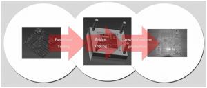
The main reason people manufacture rapid tooling is for testing and validation of parts in the prototyping stages of new product development. Although other prototyping options such as 3D printing, CNC or vacuum casting would generally allow faster and cheaper prototypes the main advantage of rapid tooling lies in the process and materials.
Rapid tooling allows you to use the actual production grades of material, allowing you a much clearer picture of how the parts will act in real world applications and enabling you to test and confirm you have made the correct material choices. Parts are also injection molded as they would be in production so you can also use them for stress and impact testing for example, exploring any weak areas due to weld lines or other imperfections from the injection molding process such as shrink and warping. With this information you can then better determine if any changes need to be made before expensive production tooling.
People also use rapid tooling to test the parameters of production, and ensure they will get parts that fill correctly and act as desired. In this way engineers and designers are able to catch a lot of future process flaws and implement redesigns or other measures to prevent issues with the final parts.
There are a number of other reasons for selecting rapid tooling, other than the prototyping and testing already mentioned. Principally it is a low cost, rapid option for manufacturing injection molded parts. The advantages of speed allow you to get parts to market quickly, and the cost advantages allow both market testing and mean it is a suitable choice for lower volume production runs.
In terms of how to make a rapid tool there are many different approaches depending on the part and requirements but the general idea is to reduce as far as possible the time taken and costs involved in the manufacture. This includes various techniques such as;
– utilising standard mold bases and just manufacturing inserts
– using aluminium or soft steels which machine faster
– cutting out extra processes such as EDM
– using low cost components
– manual inserts
An emerging option is also to use 3D printing in both plastics and metals to replace a lot of the conventional parts of the tools but this is still a long way from being truly competitive for a number of reasons.
Different companies approach the manufacture of rapid tools in different ways but the very nature of rapid tooling and product development process means most specialist companies are able to offer a level of flexibility to achieve what you need.
So what you need to know when trying to source a rapid tool manufacturer for your project? Essentially you need to be very clear on what exactly you are after. Obviously the increased speed and lower costs of rapid tooling compared to conventional production tooling are also going to impact somewhat on the final parts, but as long as you know what you are looking for and make your requirements clear to the manufacturer you should be able to avoid surprises.
Rapid tooling is known by many names including prototype tooling and soft tooling, but it is essentially pared back injection mold tooling enabling you to quickly and cheaply get parts.
It is important to differentiate between the concept and the realization as there are many ways of achieving the same results.
Conceptually it is any type of injection mold tooling, manufactured quickly and inexpensively to enable testing and validation of parts before you invest in production tooling.
In terms of realization, anything that allows you to do this can apply.
The main reason people manufacture rapid tooling is for testing and validation of parts in the prototyping stages of new product development. Although other prototyping options such as 3D printing, CNC or vacuum casting would generally allow faster and cheaper prototypes the main advantage of rapid tooling lies in the process and materials.
Rapid tooling allows you to use the actual production grades of material, allowing you a much clearer picture of how the parts will act in real world applications and enabling you to test and confirm you have made the correct material choices. Parts are also injection molded as they would be in production so you can also use them for stress and impact testing for example, exploring any weak areas due to weld lines or other imperfections from the injection molding process such as shrink and warping. With this information you can then better determine if any changes need to be made before expensive production tooling.
People also use rapid tooling to test the parameters of production, and ensure they will get parts that fill correctly and act as desired. In this way engineers and designers are able to catch a lot of future process flaws and implement redesigns or other measures to prevent issues with the final parts.
There are a number of other reasons for selecting rapid tooling, other than the prototyping and testing already mentioned. Principally it is a low cost, rapid option for manufacturing injection molded parts. The advantages of speed allow you to get parts to market quickly, and the cost advantages allow both market testing and mean it is a suitable choice for lower volume production runs.
In terms of how to make a rapid tool there are many different approaches depending on the part and requirements but the general idea is to reduce as far as possible the time taken and costs involved in the manufacture. This includes various techniques such as;
– utilizing standard mold bases and just manufacturing inserts
– using aluminum or soft steels which machine faster
– cutting out extra processes such as EDM
– using low cost components
– manual inserts
An emerging option is also to use 3D printing in both plastics and metals to replace a lot of the conventional parts of the tools but this is still a long way from being truly competitive for a number of reasons.
Different companies approach the manufacture of rapid tools in different ways but the very nature of rapid tooling and product development process means most specialist companies are able to offer a level of flexibility to achieve what you need.
So what you need to know when trying to source a rapid tool manufacturer for your project? Essentially you need to be very clear on what exactly you are after. Obviously the increased speed and lower costs of rapid tooling compared to conventional production tooling are also going to impact somewhat on the final parts, but as long as you know what you are looking for and make your requirements clear to the manufacturer you should be able to avoid surprises.
 Vacuum casting or urethane casting is ideal for prototyping and low volume production runs of plastic parts. It is a versatile but often overlooked process so here is a quick look at how it works, what it is best for and where it falls down when compared to other processes.
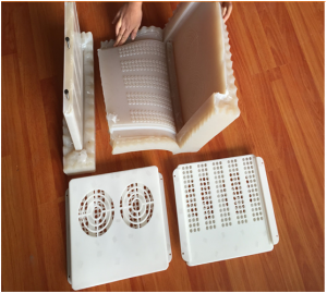
Vac casting is labor intensive but still allows for fast turnaround times. Step one involves making a master model, often by SLA or CNC. These are then hand finished producing the desired surface, it is at this stage you can apply certain textures or polish for a very glossy look.
Step two sees the master model suspended in a container and covered with liquid silicone which hardens to form the mold. The original is then cut from the tool to leave a cavity inside.
Step three is to cast the parts. A wide range of polyurethanes are available. An A and B material are mixed together and then poured into the tool cavity, the whole thing is then cured in a vacuum to get rid of the air bubbles.
The final stage is to remove and finish the parts which might have a lot of flash due to the soft tool material.
You can the rerun the final two steps to cast further reproductions.
Depending on the type of silicone used for the tools the tolerance and finish required and the geometry of the parts you can generally get between ten and twenty reproductions from each tool.
So that’s how the parts are made but what about the relative strengths and weaknesses vs alternative technologies.
Vacuum casting is great when you need low volumes of parts relatively quickly, the master models are produced quickly especially if 3D printed and tooling is no more than one day. The casting process generally takes a few hours per cycle then depending on the finish you require they need a little cleaning up and they are good to go. This rapid turnaround time beats most other technologies and is often the only way to get the parts you need in a hurry.
Other advantages include part pigmentation, giving a finish similar to injection moldings. You can also apply a range of surface textures that would not be an option for CNC machined parts.
As the tools are silicone, which is soft often complex geometries which could have meant splitting the parts for CNC machining become possible for vacuum casting. There are also soft, rubber like materials available so rubber parts and over-molding is possible.
The tools are cheap so the initial investment is lower when compared to injection molding, allowing for low cost market testing and many rapid design iterations.
There are some disadvantages though, principally the material selection, which is limited to polyurethanes. PU materials are available in many different types which have characteristics similar to other plastics such as ABS, PP or acrylic but they are still PU which as far as I understand are still not recyclable.
The process is labor intensive so once you get into the high tens and hundreds of parts it might be better switching to rapid tooling which despite the higher tooling costs could be cheaper.
The parts can be self colored but this pigmentation is generally done by hand/eye and means often the results are difficult to control. This means if you need an exact color match you may still need to paint the parts.
The silicone tools are soft and often the parts have a lot of flash that needs cleaning up, this can also affect the tolerances you can hold so it is not really a good fit where high precision is required.
Vacuum casting is great for prototypes and low volume production runs of plastic parts for development and engineering or market testing. It is a flexible process delivering good results and as long as you understand the limitations and select it only when it makes sense you should be safe.
 There are many supplier choices when it comes to manufacturing parts and prototypes. Some are fast, some are good and some are cheap but no matter which you choose there are some key steps you should take and questions you should ask to ensure you get the parts you require.
The responsibility for quality is too often left entirely to the supplier and while the lion’s share does lie with them quality is not entirely one sided. In order to deliver what you need the shop you are working with needs to know what you want. It is as important for you to provide as much information as possible up front as it is for the prototype shop to perform proper checks after manufacture.
Here are some simple steps to take to make sure everyone knows what is expected and will hopefully reduce surprises when your parts arrive.
Pre-order steps to take;
– Send 2D engineering drawings with critical dimensions and tolerances clearly marked
– Indicate clearly any holes that need tapping and as far as possible stick to standard threads
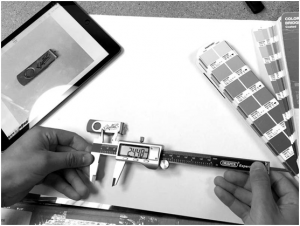
– Clearly specify surface finish and send a photo example if possible if you are not referring to an industry standard
– Send assembly drawings if applicable or as far as possible provide information about assembly especially if there are other mating parts you might not have sent to the shop for manufacture
– Offer as much information on fit and function as you can and feel comfortable with, the more your supplier know about the part the better they will be able to deliver
– Be as open and upfront about what the part is, what is important and what you are looking for as possible
– Remember the time, price, quality triangle, and try not to expect all three. As long as you are clear about your priorities the prototype shop should be able to tweak their quote to fit
Questions to ask after manufacture and before delivery;
– Do you have a QC report you can send?
– How many parts did you check, one or all?
– Are all threads present and correct
– Please send clear pictures of all parts, plus close ups of any suspect areas
– Can you send a video of the assembly
Most of these steps and questions may seem obvious and it is to be hoped the company you are working with is asking for and providing this anyway, but as long as you are on top of these points with all your suppliers you should consistently receive quality parts to your specifications.
Prototyping is often high speed and lead times are key, often shops are up against the wall. This sometimes means in the rush to get parts out the door sometimes things are missed at both sides. What gets measured gets done as the saying goes so make sure you are providing as much information up front as possible and then requiring checks at the back end.
There might be a tendency to only reveal certain information to your suppliers in order to try obtain better prices or to protect IP. These are issues you need to consider but there is nothing worse during a high profile project than to get a batch of non-conforming parts you cannot use and have to send them back for rework causing massive delays.
As long as you are clear on your requirements’ and remind the shop about required checks before shipping you should be ok. Also remembering you are in a partnership and sharing as much as possible with your suppliers will enable them to do their jobs much better.
 Prototyping is a key stage in most product development timelines and there are many different ways of manufacturing them. Below are four of the most common methods and their respective advantages and disadvantages.
CNC machining is a subtractive process where three dimensional CAD drawings are used to produce tool paths which are fed into computer controlled mills and lathes, which take a block of material and use a series of bits and cutters to cut away at it until you are left with the part you want. These machined parts can then be finished and dressed using a series of post process finishing options.
CNC machining is one of the most common methods for making prototypes and offers a number of distinct advantages over other processes.
The material choices available are fairly comprehensive and include both plastics and metals. The materials are also available in grades offering a close approximation of production materials.
CNC machining can hold tight tolerances and so offers precision parts for assembly and mechanical testing.
A range of surface finish options are available on CNC machined parts offering greater flexibility and allowing you to replicate production parts and models.
In terms of the downsides, it is often limited in terms of the geometries possibly, unless you are open to splitting the parts which is not always an option depending on the type of material desired.
Also once the parts have been machined they may require some hand finishing and prep work if they are going to be finished, this can sometimes increase lead times quite considerably and is often expensive.
Vacuum casting is also known as silicone tooling, or urethane casting. Here the most common process involves using a CNC machined or 3D printed master model to produce a silicone tool. The master model is then cut from the tool leaving a cavity in the shape of the required part. The tool is then used to reproduce parts from A/B urethane materials, a vacuum is used to remove air bubbles and the parts are baked hard.
This is a great process for low volume production runs or prototypes, often working out much cheaper than alternatives. It allows you to experiment more in the run up to locking down a final shape as the tooling is much cheaper than steel.
It allows you to realize in one piece certain parts CNC machining could not manage without splitting and also allows for parts from rubber like materials.
You can self-color the parts instead of painting and even over mold two materials together.
There are a number of disadvantages too though, it can often be very expensive, especially for big parts or once you get up into higher numbers of reproductions.
The materials although varied in characteristics are all polyurethanes.
The parts don’t tend to hold up too well under certain environmental conditions and tend to warp and discolor over time.
3D Printing – as a technology 3D printing has been around and used for decades, but it has really taken off over the last couple of years with a spate of new cheaper technologies and numerous new material options.
Additive manufacturing now comprises technologies building parts out of both plastics and metals but as metal 3D printing is still a specialized technology and for the most part beyond most people’s budgets we will stick to plastics here. In terms of the mechanical part building and prototyping spheres there are three main technologies with numerous others in the background that either can’t compete or are not there yet. The main additive processes are FDM, SLA and SLS.
SLA and SLS are the most widely used industrially and are similar in that they use lasers directed at a build area to precisely cure or fuse material together one layer at a time. The most simplified description of the differences between the two is SLA is a liquid resin material and SLS is powder.
FDM is a different process and one which allows for consumer level equipment. Here molten plastic filament is extruded and deposited one layer at a time building parts from the bottom up.
Each of these technologies each has its own unique list of advantages and disadvantages but to take 3D printing as a whole the process is fast, increasingly inexpensive and accurate. It allows you to build precise models with complex geometries and depending on the process and material can be used for mechanical parts in assemblies.
In terms of the disadvantages, the material selection is fairly limited and it can often work out expensive when compared to other processes.
Rapid Tooling, this is often not considered a prototyping process but there are many times when using the actual part material produced under as close to production conditions as a possible is the only way to truly test the parts. Rapid tooling or Prototool is low volume, low cost injection mold tooling. The tools are sometime made from aluminum or a low grade steel and any side actions are generally manual to keep costs down. Often small changes to the geometry of the parts to reduce or remove tool manufacturing stages can be made to reduce time and keep costs down.
Rapid tooling allows you to use the production material or even to trial a number of different grades or brands. It also replicates the production process and so part should have all the weaknesses and flaws it will in production to allow for more accurate functional testing. Despite the upfront tooling costs rapid tooling can also work out much cheaper than other processes for certain parts, especially once you move up past 100 pcs.
On the downside if you do just want a few parts for testing the tooling costs can be probative and no matter how rapid the tooling process the build time is often much longer than a 3D printed or machined sample would be.
There are many other ways of manufacturing prototypes and the four listed above have a number of other advantages and disadvantages not mentioned. As always I welcome comments and questions below.
 Designing for CNC machining when prototyping.
CNC machining is one of the most utilized manufacturing processes for prototypes and low volume production runs. It offers great advantages in terms of speed and range of materials available and is also fairly cost effective when compared to other processes. CNC is highly versatile and especially with 3,4 and 5 axis machines the type of part and geometries able to be machined are varied. That said it also pays to be aware of certain design elements which could reduce the machining time, complexity and cost of your job.
First and most simply the type of material has a big impact upon cost. CNC machines can cut everything from plastics to metals but there are some materials which are easier to work with than others.
If we take plastics first of all there are a number of common and easy to machine grades of plastic, ABS for example is cheap, versatile and very machinable. On the other hand PP or POM is more difficult to cut and prone to warping, which means the manufacturing process is quite a bit more complicated increasing the costs.
Metal materials also offer different ranges of machinability, aluminum is a fairly soft metal and so easy to cut and quick to machine. Steel is a much harder material and so much tougher on the machines, this is often reflected in the prices of the parts.
The next thing to consider is the part geometry, here there are so many different aspects to consider it would be impossible to list them all but here is a quick summary of a few.
Corner radii, CNC machine cutter tools are circular, so even the smallest diameter cutter is going to leave a radius in the corner. If you need square corners this will require post process finishing either by hand on plastic parts or spark erosion on metals. If you can get away with radii, and the bigger the better, you can bring the costs of machining down a little.
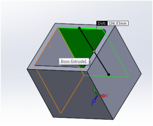
Deep pockets, these are also tricky to machine and often result in tool chatter leaving you with imperfect surface finishes. If you can do away with these kinds of features all the better, if not the best ratio between length to depth is 4:1.
Thin walled features are also tricky to machine and easy to become damaged so machinists generally don’t like them.
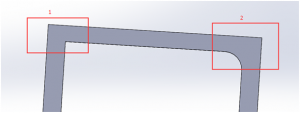
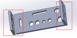
For some parts it may also make sense to split them into several separate parts if they are to be machined. Where machining in one piece might have advantages in terms of strength and cosmetic benefits often if you can accept the part being split you can save some money. Compare areas 1 and 2 in the image below. In this instance it may make sense to split the part as area 2 makes the part more difficult to machine, increases the initial material costs and would require an additional machine setup.
Other issues which drive up costs are the tolerances required on the parts, obviously the higher the desired tolerances the more care and attention needed when machining the part. Very high tolerances on certain features may also require the manufacture of special jigs and fixtures to hold the work piece or even the use of specialized cutting tools which will all increase machining time and costs.
This is also the case for threads and tapped parts, if you do need threaded holes try as far as possible to stick to standard threads.
One way of driving individual part costs down a little is to order multiples. Once the tool paths for the part have been programmed the CNC machine can run the same parts over again allowing economies of scale.
CNC machined parts offer versatility of material, high precision, great surface finish and speed. If anyone can think of any other ways to drive CNC machine part costs down pelase do leave a comment below.